
What Is a Pressure Transmitter? Meaning, Signal Output and Features of 0–1 Bar vs. 0–4 Bar Models
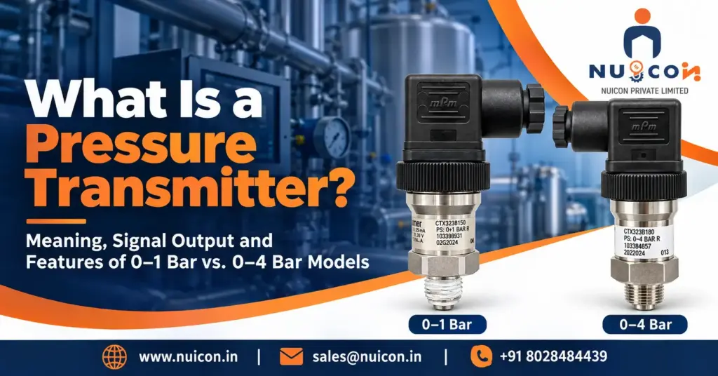
What Is a Pressure Transmitter? Meaning, Signal Output and Features of 0–1 Bar vs. 0–4 Bar Models Meaning:- A pressure transmitter measures pressure—the force per unit area exerted by a liquid or gas—and provides a conditioned electrical output for a PLC, computer or display. The Analog Analogy As a simple analogy, pressure changes the output smoothly, similar to adjusting a dimmer. The following examples assume a linear, zero-based 4–20 mA pressure scale; the transmitter does not directly drive a lamp. Zero pressure = 4 mA. This is a live zero: the loop carries current even at the lower measurement limit. Half-scale pressure = 12 mA: 0.5 bar on a 0–1 bar model, or 2 bar on a 0–4 bar model. Full-scale pressure = 20 mA: 1 bar on a 0–1 bar model, or 4 bar on a 0–4 bar model. Why is it called a “Transmitter” and not just a “Sensor”? A sensing element responds to pressure through an electrical or mechanical change. The terms sensor, transducer and transmitter overlap in commercial usage. A transmitter includes conditioning electronics and a specified output, such as 4–20 mA. Current loops support remote measurement within their voltage and resistance limits. Correct installation reduces interference, but no transmission method is immune to all noise or wiring faults. 0–1 Bar Pressure Transmitter Features A 0–1 bar model provides a 1 bar measuring span. Suitability depends on the required pressure type, accuracy and application conditions, rather than an assumed trade-off between sensitivity and strength. Sensing Construction: Metallic, ceramic and other sensing designs are available. Range alone does not determine diaphragm thickness or guarantee suitability for low-velocity air measurement. Signal Sensitivity: A linear 4–20 mA version provides 16 mA/bar. This gives four times the current change per bar of a 0–4 bar version. Actual resolution and accuracy remain product- and receiver-dependent. Overpressure Capability: Check the specified permissible overload and burst pressure. Do not assume a 2–3 bar limit from a 0–1 bar measuring range. Burst pressure is not an allowable operating pressure. Pressure Reference: A vented gauge model measures relative to local atmosphere; protect its reference arrangement as instructed. Absolute-pressure and other reference types differ. Atmospheric venting is not unique to the 0–1 bar range. 0–4 Bar Pressure Transmitter Features A 0–4 bar model provides a measuring span four times wider than a 0–1 bar model. It may suit regulated air, water or lubrication services within its specifications. Sensing Construction: Technology and mechanical durability depend on the product family. A thicker diaphragm or more robust sensing die cannot be assumed from the range alone. Measuring Span: A 0–4 bar model covers a 2–3 bar operating condition that is outside a 0–1 bar span. Allow for actual maximum pressure and transients when selecting the instrument. Overpressure Capability: Use manufacturer-specified limits rather than assuming an 8–12 bar proof rating. Confirm how the manufacturer defines overload, proof and burst pressure and any limits on exposure. Pulsation Protection: Check dynamic-pressure suitability. Water hammer and pump pulsations may require a specified snubber, damper or other protection. Internal fill fluid, where present, primarily transmits pressure to the sensing element. Comparison of Core Features Feature 0–1 Bar Transmitter 0–4 Bar Transmitter Primary Focus A 1 bar measuring span; ideal current sensitivity 16 mA/bar. A 4 bar measuring span; ideal current sensitivity 4 mA/bar. Burst Pressure Model-specific; verify the datasheet. Not a permissible operating limit. Model-specific; verify the datasheet. Not a permissible operating limit. Diaphragm Thickness Design-specific; cannot be inferred from range alone. Design-specific; cannot be inferred from range alone. Best Used For Suitable vented-tank level, test rigs or gas services; confirm range, accuracy and materials. Duct air usually requires a much lower range. Suitable regulated air branches, water circuits or lubrication lines within the specified range and ratings. Selection note: compare accuracy on the same basis. For illustration, ±0.5% of span equals ±0.005 bar on a 0–1 bar instrument and ±0.020 bar on a 0–4 bar instrument. These are examples, not specifications for a particular product. Recent Posts What Is a Pressure Transmitter? Meaning, Signal Output and Features of 0–1 Bar vs. 0–4 Bar Models October 24, 2026 How a 0–4 Bar Pressure Transmitter Works: Internal Components and Installation Materials The following describes common construction options and installation… Read More → How a Pressure Transmitter Works: Meaning, Uses, Benefits, Risks of Not Using One, and 0–1 Bar vs. 0–4 Bar Comparison. October 24, 2026 How a Pressure Transmitter Works: Meaning, Uses, Benefits, Risks of Not Using One, and 0–1 Bar vs. 0–4 Bar Comparison… Read More → How a 0–4 Bar Pressure Transmitter Works: Internal Components and Installation Materials October 24, 2026 How a 0–4 Bar Pressure Transmitter Works: Internal Components and Installation Materials The following describes common construction options and installation… Read More → How a 0–4 Bar Pressure Transmitter Works in Pneumatic Systems, Water Treatment, Heating and Cooling Loops, Lubrication and Low-Pressure Hydraulics October 24, 2026 How a 0–4 Bar Pressure Transmitter Works in Pneumatic Systems, Water Treatment, Heating and Cooling Loops, Lubrication and Low-Pressure Hydraulics… Read More → REQUEST A QUOTE
How a Pressure Transmitter Works: Meaning, Uses, Benefits, Risks of Not Using One, and 0–1 Bar vs. 0–4 Bar Comparison.
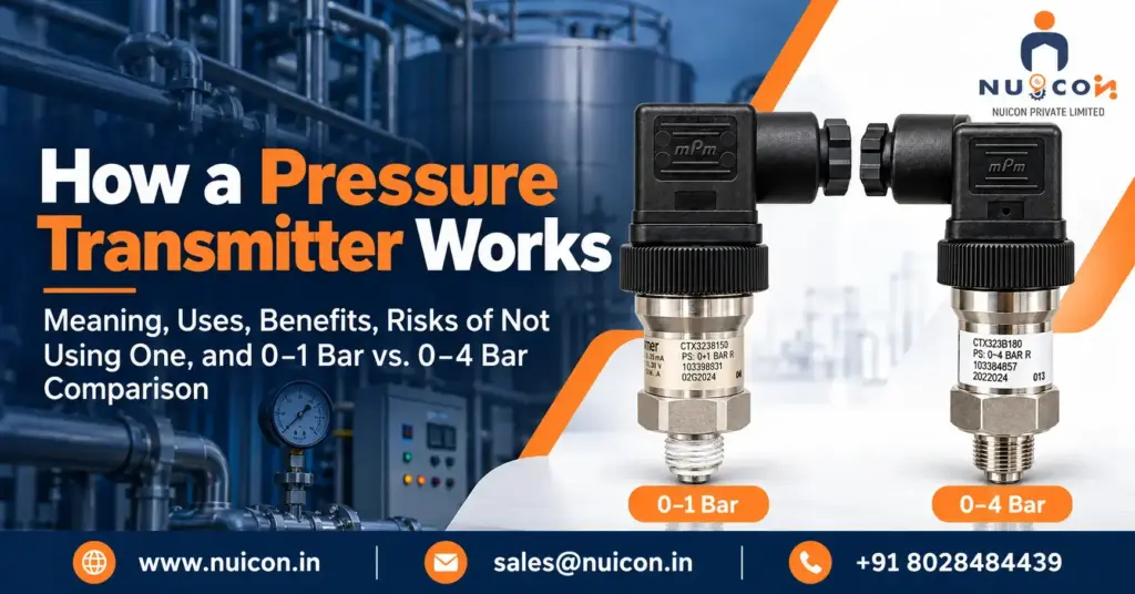
How a Pressure Transmitter Works: Meaning, Uses, Benefits, Risks of Not Using One, and 0–1 Bar vs. 0–4 Bar Comparison Meaning:- A pressure transmitter measures the pressure of a liquid or gas and converts it into a standardised electrical signal, such as 4–20 mA, for a controller or display. Pressure is force per unit area. Essentially, it acts as the “eyes” for a computer system, translating real-world pressure into data. Working principle:- A sensing assembly responds to applied pressure, and internal electronics convert its response into the specified current, voltage or digital output. Here is the step-by-step breakdown of how it works, followed by the differences between a 0–1 bar and a 0–4 bar transmitter. Step-by-Step Operation:- Pressure Application: The process fluid (liquid or gas) enters the transmitter’s inlet and presses against a flexible sensing diaphragm. Mechanical Deflection: The physical pressure causes the diaphragm to bend slightly. More pressure equals more deflection. Sensor Conversion: The diaphragm’s movement changes an electrical property in an internal sensor. This is usually done via a piezoresistive sensor (where resistance changes with strain) or a capacitive sensor (where the distance between two plates changes). Signal Conditioning: An internal circuit measures this micro-change in resistance or capacitance and converts it into a standardized linear electrical signal. Output Transmission: The transmitter sends this final signal (e.g., 4–20 mA) to a controller like a PLC or a digital display. Comparison: 0–1 Bar vs. 0–4 Bar Transmitters Both ranges may use the same sensing technology within a product family, but this is not guaranteed. The definite difference is the calibrated pressure span; construction, accuracy, resolution and overload limits require datasheet confirmation. Feature 0–1 Bar Transmitter 0–4 Bar Transmitter Pressure Range Measures low pressures from 0 to 1 bar (approx. 0 to 14.5 psi). Measures 0–4 bar, approximately 0–58 psi or 0–400 kPa. Diaphragm Design Depends on sensor technology and manufacturer; a thinner diaphragm cannot be assumed from the range alone. Depends on sensor technology and manufacturer; a thicker diaphragm cannot be assumed from the range alone. Electrical Scaling (4–20 mA example) • 4 mA = 0 bar • 12 mA = 0.5 bar • 20 mA = 1 bar • 4 mA = 0 bar • 12 mA = 2 bar • 20 mA = 4 bar Resolution & Sensitivity Ideal current sensitivity: 16 mA/bar. Actual resolution and accuracy depend on the transmitter and receiver. Ideal current sensitivity: 4 mA/bar. With otherwise identical electronics, percentage-of-span resolution may be similar, while resolution in bar differs. Overpressure Limit Use the model-specific permissible overload and burst-pressure values. Neither is established by the measuring span alone. Use the model-specific permissible overload and burst-pressure values. A wider span does not guarantee resistance to water hammer. Benefits and Risks of Pressure MonitoringPressure feedback can support remote indication, alarms, process control and troubleshooting. The consequences of inadequate monitoring depend on the process and other safeguards. Mechanical gauges, pressure switches and independent protective devices may also form part of the design. Financial and Operational Impacts Equipment Protection: Suitable monitoring can help identify abnormal pressure and initiate designed responses. A transmitter alone does not prevent pump damage, boiler overpressure or pipe failure; relief devices and other protection remain application-specific. Production Downtime: Unexpected pressure variations can disrupt production. Trends and configured alarms may help operators identify problems earlier, although financial impact varies by installation. Product Quality: Pressure control can improve consistency in processes such as dosing, packaging and mixing. The benefit depends on the process and the complete control loop. Safety and Compliance Risks Safety and Compliance: Pressure feedback may support a protective function only when the complete system is designed and validated for that purpose. The applicable requirements depend on the installation; a general-purpose transmitter is not automatically a safety-rated device. Operator Workload: Remote indication and logging can reduce routine manual readings and improve visibility, while local gauges and inspections may still be required. Energy Use: Appropriate pressure feedback can help pumps, compressors and HVAC equipment meet demand efficiently. Savings depend on control strategy and actual operating conditions. Recent Posts How a Pressure Transmitter Works: Meaning, Uses, Benefits, Risks of Not Using One, and 0–1 Bar vs. 0–4 Bar Comparison. October 24, 2026 How a 0–1 Bar Pressure Transmitter Works: Internal Components and Installation Materials The following describes common construction options and installation… Read More → How a 0–4 Bar Pressure Transmitter Works: Internal Components and Installation Materials October 24, 2026 How a 0–4 Bar Pressure Transmitter Works: Internal Components and Installation Materials The following describes common construction options and installation… Read More → How a 0–4 Bar Pressure Transmitter Works in Pneumatic Systems, Water Treatment, Heating and Cooling Loops, Lubrication and Low-Pressure Hydraulics October 24, 2026 How a 0–4 Bar Pressure Transmitter Works in Pneumatic Systems, Water Treatment, Heating and Cooling Loops, Lubrication and Low-Pressure Hydraulics… Read More → How a 0–1 Bar Pressure Transmitter Works: Internal Components and Installation Materials October 24, 2026 How a 0–1 Bar Pressure Transmitter Works: Internal Components and Installation Materials The following describes common construction options and installation… Read More → REQUEST A QUOTE
How a 0–4 Bar Pressure Transmitter Works: Internal Components and Installation Materials
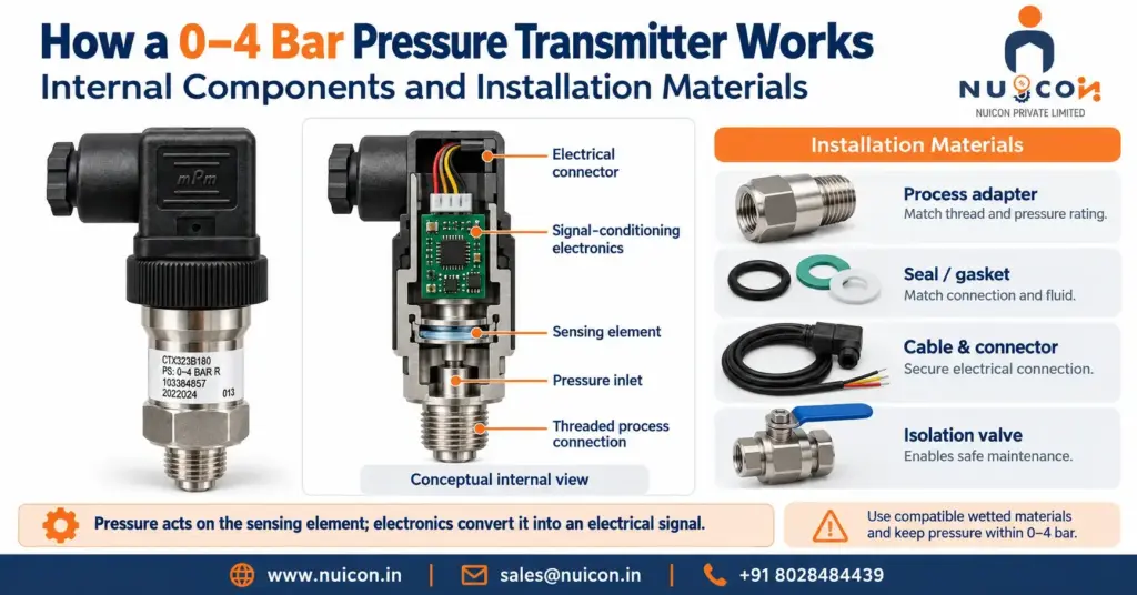
How a 0–4 Bar Pressure Transmitter Works: Internal Components and Installation Materials The following describes common construction options and installation accessories. The exact components and required accessories depend on the selected model and application. Internal Components (Inside the Transmitter) Manufacturers combine a sensing assembly and signal-conditioning electronics; the construction varies between product families. Sensing Element: Common options include piezoresistive silicon, ceramic thick-film, metal thin-film and capacitive designs. Pressure changes resistance or capacitance depending on technology. Range alone does not establish diaphragm thickness, accuracy or overload capability. Process Diaphragm: The pressure-sensitive or isolating surface may be metallic or ceramic. Examples include stainless steel, alumina ceramic and specialist alloys. Verify all wetted materials, including seals, for the process fluid and temperature. Internal Fill Fluid (where used): In some isolated sensing assemblies, a liquid transmits pressure from the process diaphragm to the sensing element. Other designs are oil-free. Fill fluid is not a general substitute for pulsation protection. Oxygen service requires manufacturer-approved materials, cleanliness and construction; oil type alone is insufficient. ASIC/Circuitry: An integrated circuit board that processes the sensor’s physical deflection and calibrates it linearly across the 0 to 4 bar span, outputting a standard industrial signal (e.g., 4–20 mA, 0–10 V, or Modbus). Housing/Enclosure: Material and ingress protection depend on the product and environment. Select suitable protection for dust, washing, condensation or immersion. The stated rating may require the correct mated connector and cable installation. Atmospheric Reference: A vented gauge-pressure transmitter references local atmospheric pressure through an arrangement determined by its design. Protect the reference path from blockage and moisture according to the installation instructions. Absolute-pressure versions use a different reference. External Materials (Needed for Installation & Operation) Provide the accessories required by the installation; adapters and impulse tubing are unnecessary where a suitable direct connection is available. 1. Mechanical Piping & Process Connection Process Fitting: Match the exact transmitter connection, sealing face and pressure/temperature rating. Common options include G1/4, G1/2, 1/4 NPT and 1/2 NPT, but these are not interchangeable. Sealing Material: For tapered NPT connections, use an approved thread sealant where specified and avoid contaminating the pressure port. For parallel G connections, use the specified face seal, washer or O-ring. Choose FKM, EPDM, metal or another material by chemical compatibility, temperature and connection design; 4 bar alone does not determine the correct seal. Isolation Valve (where required): Select a compatible valve for the maximum possible pressure and temperature, including abnormal conditions. Provide safe depressurisation before removing or calibrating the transmitter; closing a valve alone may leave trapped pressure. Siphon, Cooling Element or Snubber (where required): Check the permissible medium temperature and transient pressure. A suitable siphon can protect an instrument in steam service; cooling elements or remote mounting may suit other hot services. A specified snubber or pulsation damper may be required for pressure spikes. Select and install accessories for the actual process. 2. Electrical Materials Power Supply: 24 VDC is common, but use the model’s specified voltage range. For a two-wire loop, allow sufficient voltage for the transmitter, receiver, wiring resistance and any barriers or isolators. Cabling / Wiring: Use the specified cable and wiring arrangement. A two-wire 4–20 mA transmitter commonly uses a twisted pair; voltage or digital versions may need additional conductors. Correct shielding and routing reduce electromagnetic interference. Select conductor size for loop resistance and installation conditions. Mating Connector: Match the specified connector form, pinout, seal and protection rating, such as the applicable EN 175301-803 (formerly DIN 43650) form or M12 version. For hazardous areas, the transmitter and installation must have appropriate approvals; a certified gland does not upgrade an ordinary transmitter. 3. Control & Monitoring System Receiver Device: A PLC (Programmable Logic Controller) analog input card, a DCS, or a Digital Panel Indicator calibrated to read the electrical output and map it to a display of 0.0 to 4.0 bar. Grounding / Shielding: Follow the manufacturer’s instructions and plant bonding requirements. Use any specified earth terminal and terminate shields as designed. Correct bonding reduces electrical risks and interference; it does not guarantee elimination of stray voltages. Installation note: follow the model’s instructions for mounting, wiring, shielding, bonding and commissioning. Confirm zero and span scaling against the receiver and use pressure protection where the application requires it. Recent Posts How a 0–4 Bar Pressure Transmitter Works: Internal Components and Installation Materials October 24, 2026 How a 0–1 Bar Pressure Transmitter Works: Internal Components and Installation Materials The following describes common construction options and installation… Read More → How a 0–4 Bar Pressure Transmitter Works in Pneumatic Systems, Water Treatment, Heating and Cooling Loops, Lubrication and Low-Pressure Hydraulics October 24, 2026 How a 0–4 Bar Pressure Transmitter Works in Pneumatic Systems, Water Treatment, Heating and Cooling Loops, Lubrication and Low-Pressure Hydraulics… Read More → How a 0–1 Bar Pressure Transmitter Works: Internal Components and Installation Materials October 24, 2026 How a 0–1 Bar Pressure Transmitter Works: Internal Components and Installation Materials The following describes common construction options and installation… Read More → How a 0–1 Bar Pressure Transmitter Works in HVAC, Liquid Tanks, Laboratory Equipment and Gas Lines October 24, 2026 How a 0–1 Bar Pressure Transmitter Works in HVAC, Liquid Tanks, Laboratory Equipment and Gas Lines A 0–1 bar pressure… Read More → REQUEST A QUOTE
How a 0–4 Bar Pressure Transmitter Works in Pneumatic Systems, Water Treatment, Heating and Cooling Loops, Lubrication and Low-Pressure Hydraulics
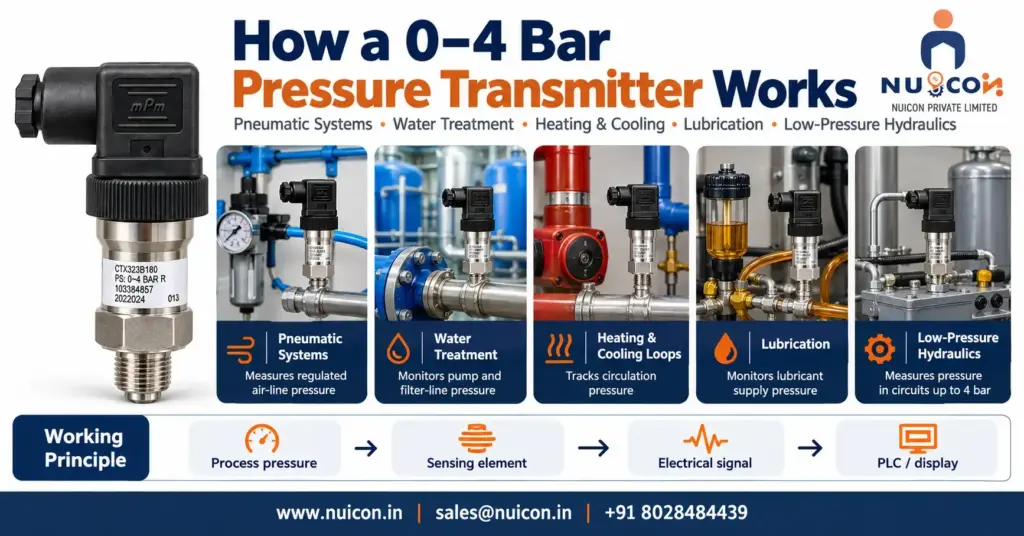
How a 0–4 Bar Pressure Transmitter Works in Pneumatic Systems, Water Treatment, Heating and Cooling Loops, Lubrication and Low-Pressure Hydraulics A 0–4 bar pressure transmitter measures pressure from 0 to 400 kPa (approximately 58 psi) and converts it into a specified electrical signal, commonly 4–20 mA. Sensor construction, accuracy, overload limits and resistance to pulsation depend on the model. The examples below assume a gauge-pressure instrument with a linear 0–4 bar, 4–20 mA output. The following applications are suitable only when normal pressure, maximum possible pressure, temperature and material compatibility meet the instrument specifications. 1. Pneumatic Systems (Compressed Air Networks) In factory automation, assembly lines, and workshops, 0–4 bar transmitters act as the primary monitoring eyes for regulated tool air and pneumatic actuation lines. Example: a regulated air branch operating at 3 bar produces an ideal 16 mA signal on a 0–4 bar transmitter. The Problem: Some pneumatic branches operate below 4 bar, while many industrial air systems operate above this range. Insufficient pressure can reduce actuator force; excessive pressure can damage components. Select the range for the actual branch and maximum possible pressure. How the Transmitter Works: Install the transmitter at an appropriate tapping downstream of the regulator. Consider regulator failure and upstream pressure exposure when specifying overload protection and equipment ratings. Compressed air acts on the sensing assembly. The sensing technology and diaphragm material depend on the selected model. At 3 bar, the ideal output is 16 mA: 75% of the 16 mA measurement span above the 4 mA zero. The System Reaction: A PLC can monitor the signal and apply configured alarms or interlocks. At 1.5 bar the ideal output is 10 mA. Actual alarm thresholds, delays and machine responses must suit the equipment and control design. 2. Water and Wastewater Treatment In filtration systems, chemical dosing lines, and lift stations, these transmitters track pump performance and pipe integrity. Example: a compatible water-pressure transmitter provides feedback to a controller that adjusts pump speed to a selected pressure setpoint. The Problem: Pumps must provide the pressure required for flow and treatment while remaining within piping and equipment limits. Required pressure varies with the system. How the Transmitter Works: The transmitter is plumbed into the discharge manifold of a pump or right before an industrial filter. Select wetted materials and seals for the water chemistry, chemicals, solids and cleaning conditions. Flush-diaphragm designs may suit some services with solids. Stainless steel or ceramic is not universally resistant to all wastewater conditions. Process pressure acts on the sensing assembly. At 2 bar, the ideal output is 12 mA on a 0–4 bar transmitter. The System Reaction: At 3.8 bar, the ideal output is 19.2 mA. High upstream pressure may trigger a configured alarm but does not by itself prove filter blockage. Monitor pressure difference across the filter, together with relevant operating conditions, when assessing loading or initiating backwash. 3. Cooling and Heating Loops (HVAC Chilled/Hot Water) A 0–4 bar transmitter may monitor a hydronic circuit where the normal and maximum pressures fit its specifications. Taller buildings or higher-pressure systems may require a wider range. Example: loop pressure is measured, displayed by the BMS and compared with configured alarm or control limits. The Problem: Hydronic systems require sufficient pressure at high points and must stay within equipment limits. Required fill pressure depends on elevation, temperature and system design; 2–3 bar is an example rather than a universal requirement. How the Transmitter Works: Connect the transmitter at the designated pressure tapping. Check medium and ambient temperature limits. Use a suitable cooling element, connecting line or other approved arrangement only where required; a pigtail siphon is not mandatory for every hot-water installation. Static liquid head, pump operation and thermal expansion can affect pressure at the sensing point. A gauge-pressure transmitter measures fluid pressure relative to local atmosphere. The reading also depends on the tapping elevation within the liquid circuit. Pump differential-pressure control requires the appropriate pressure difference measurement. The System Reaction: A low-pressure reading can initiate an alarm or an equipment-specific protective response. On this scale, 1 bar equals an ideal 8 mA. Shutdown setpoints and any additional flow or low-water protection must follow the equipment and system design. 4. Lubrication and Low-Pressure Hydraulics In heavy industrial machinery, wind turbines, and marine engines, these devices monitor oil feed pressures that keep massive bearings spinning smoothly. Example: lubrication pressure produces a scaled signal; the controller compares it with limits specified by the machinery manufacturer. The Problem: Lubrication pressure varies with system design, viscosity, temperature and pump operation. Required pressure and permissible startup transients must come from the machinery specifications. Most conventional power-hydraulic circuits operate above a 0–4 bar measuring range. How the Transmitter Works: Mount a compatible transmitter at the specified oil tapping. Some designs contain fill fluid for pressure transmission; others do not. Where necessary, use a suitably specified snubber or pulsation damper rather than relying on internal fill fluid to absorb pump pulsations. Cold oil can cause higher startup pressure. Although 3.8 bar is within a 0–4 bar measuring span, transient peaks, maximum possible pressure and the manufacturer’s overload rating must also be considered. The System Reaction: At 2.5 bar the ideal output is 14 mA; at 0.5 bar it is 6 mA. A controller may initiate a low-pressure alarm or protective shutdown using machinery-specific logic. Total response time includes sensing, filtering, controller processing and the final device; a millisecond shutdown is not guaranteed. Recent Posts How a 0–4 Bar Pressure Transmitter Works in Pneumatic Systems, Water Treatment, Heating and Cooling Loops, Lubrication and Low-Pressure Hydraulics October 24, 2026 How a 0–1 Bar Pressure Transmitter Works: Internal Components and Installation Materials The following describes common construction options and installation… Read More → How a 0–1 Bar Pressure Transmitter Works: Internal Components and Installation Materials October 24, 2026 How a 0–1 Bar Pressure Transmitter Works: Internal Components and Installation Materials The following describes common construction options and installation… Read More → How a 0–1 Bar Pressure Transmitter Works in HVAC, Liquid Tanks, Laboratory
How a 0–1 Bar Pressure Transmitter Works: Internal Components and Installation Materials
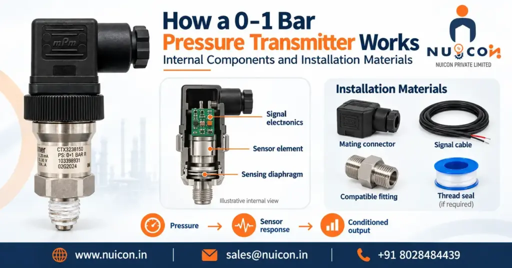
How a 0–1 Bar Pressure Transmitter Works: Internal Components and Installation Materials The following describes common construction options and installation accessories. The exact components and required accessories depend on the selected model and application. Internal Components (Inside the Transmitter) Manufacturers combine a sensing assembly and signal-conditioning electronics; the construction varies between product families. Sensing Element: Common options include piezoresistive silicon, ceramic thick-film, metal thin-film and capacitive designs. Pressure changes resistance or capacitance depending on technology. Range alone does not establish diaphragm thickness, accuracy or overload capability. Process Diaphragm: The pressure-sensitive or isolating surface may be metallic or ceramic. Examples include stainless steel, alumina ceramic and specialist alloys. Verify all wetted materials, including seals, for the process fluid and temperature. Internal Fill Fluid (where used): In some isolated sensing assemblies, a liquid transmits pressure from the process diaphragm to the sensing element. Other designs are oil-free. Fill fluid is not a general substitute for pulsation protection. Oxygen service requires manufacturer-approved materials, cleanliness and construction; oil type alone is insufficient. ASIC/Circuit Board: Internal electronics that amplify, linearize, and convert the tiny sensor fluctuations into a standard industrial signal (like 4–20 mA or 0–10 V). Housing/Enclosure: Material and ingress protection depend on the product and environment. Select suitable protection for dust, washing, condensation or immersion. The stated rating may require the correct mated connector and cable installation. Atmospheric Reference: A vented gauge-pressure transmitter references local atmospheric pressure through an arrangement determined by its design. Protect the reference path from blockage and moisture according to the installation instructions. Absolute-pressure versions use a different reference. External Materials (Needed for Installation & Operation) Provide the accessories required by the installation; adapters and impulse tubing are unnecessary where a suitable direct connection is available. 1. Mechanical Piping & Process Connection Process Fitting: Match the exact transmitter connection, sealing face and pressure/temperature rating. Common options include G1/4, G1/2, 1/4 NPT and 1/2 NPT, but these are not interchangeable. Sealing Material: Use an approved sealant for tapered threads where specified. Parallel G connections normally seal at a designated face using the specified washer or O-ring. Select seals for the medium, temperature and connection geometry; follow the manufacturer’s assembly instructions. Impulse Piping / Tubing (where required): Select compatible tubing for pressure, temperature and fluid service. Account for leaks, blockage, trapped gas or liquid, and hydrostatic offsets. Direct mounting may eliminate the need for tubing. Isolation Valve (where required): Select a compatible valve for the maximum possible pressure and temperature, including abnormal conditions. Provide safe depressurisation before removing or calibrating the transmitter; closing a valve alone may leave trapped pressure. 2. Electrical Materials Power Supply: 24 VDC is common, but use the model’s specified voltage range. For a two-wire loop, allow sufficient voltage for the transmitter, receiver, wiring resistance and any barriers or isolators. Cabling / Wiring: Use the specified cable and wiring arrangement. A two-wire 4–20 mA transmitter commonly uses a twisted pair; voltage or digital versions may need additional conductors. Correct shielding and routing reduce electromagnetic interference. Select conductor size for loop resistance and installation conditions. Mating Connector: Match the specified connector form, pinout, seal and protection rating, such as the applicable EN 175301-803 (formerly DIN 43650) form or M12 version. For hazardous areas, the transmitter and installation must have appropriate approvals; a certified gland does not upgrade an ordinary transmitter. 3. Control & Monitoring System Receiver Device: An instrument to read and scale the electrical signal, such as a Digital Panel Meter, a PLC (Programmable Logic Controller), or a DCS (Distributed Control System) input card. Loop Resistor (if applicable): A suitable 250 Ω resistor converts 4–20 mA into 1–5 V across it. Use this only with an appropriate voltage input and adequate loop voltage. Do not automatically add a resistor across a current input; account for its existing resistance and follow the receiver wiring instructions. Installation note: follow the model’s instructions for mounting, wiring, shielding, bonding and commissioning. Confirm zero and span scaling against the receiver and use pressure protection where the application requires it. Recent Posts How a 0–1 Bar Pressure Transmitter Works: Internal Components and Installation Materials October 24, 2026 Rosemount 3051 Pressure Transmitter: Full Guide The Rosemount 3051 Pressure Transmitter is an established industrial measurement solution for monitoring pressure… Read More → How a 0–1 Bar Pressure Transmitter Works in HVAC, Liquid Tanks, Laboratory Equipment and Gas Lines October 24, 2026 How a 0–1 Bar Pressure Transmitter Works in HVAC, Liquid Tanks, Laboratory Equipment and Gas Lines A 0–1 bar pressure… Read More → Rosemount 3051 Pressure Transmitter:- Full guide September 22, 2026 Rosemount 3051 Pressure Transmitter: Full Guide The Rosemount 3051 Pressure Transmitter is an established industrial measurement solution for monitoring pressure… Read More → Rosemount 4051S Pressure Transmitter:- Features, spec and applications September 19, 2026 Rosemount 4051S Pressure Transmitter: Features, Specs & Applications The Rosemount 4051S Pressure Transmitter is designed for industrial processes where accurate… Read More → REQUEST A QUOTE
How a 0–1 Bar Pressure Transmitter Works in HVAC, Liquid Tanks, Laboratory Equipment and Gas Lines
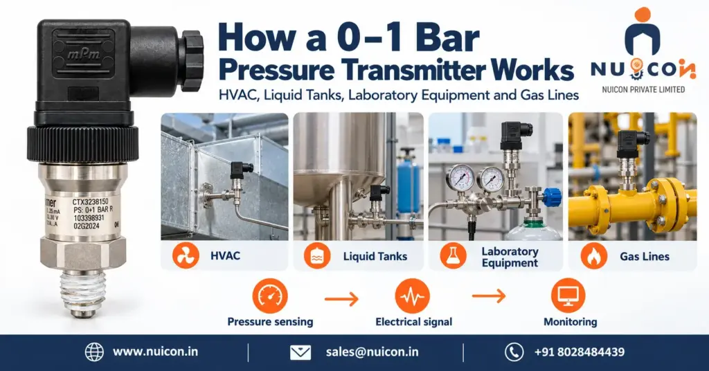
How a 0–1 Bar Pressure Transmitter Works in HVAC, Liquid Tanks, Laboratory Equipment and Gas Lines A 0–1 bar pressure transmitter measures pressure from 0 to 100 kPa (approximately 14.5 psi) and converts it into an electrical signal, commonly 4–20 mA. Accuracy, sensing technology, diaphragm construction and overload capability depend on the selected model. The examples below assume a gauge-pressure model with a linear 0–1 bar, 4–20 mA output. The following sections explain potential applications and the conditions that determine whether this range is suitable. 1. HVAC Systems (Heating, Ventilation, and Air Conditioning) In HVAC, a 0–1 bar transmitter may monitor a water circuit whose operating and maximum pressures suit the instrument. Ventilation ducts, cleanrooms and air filters usually require much lower pressure ranges expressed in pascals (Pa). A 1 bar full scale equals 100,000 Pa and is generally unsuitable for these small air-pressure differences. Example: a compatible HVAC water circuit at 0.5 bar produces an ideal 12 mA signal for a BMS. The Problem: Water-circuit pressure must remain within the system’s design limits. Separately, air-filter loading and room-pressure control require measurements of small pressure differences. How the Transmitter Works: For a suitable water circuit, the process connection transmits fluid pressure to the sensing assembly. Electronics convert the sensor response into the specified output. Choose the range for normal pressure, maximum possible pressure and required accuracy. Taller buildings or higher-pressure circuits may need a range above 0–1 bar. For ventilation filter monitoring, use a suitably ranged differential-pressure instrument connected upstream and downstream of the filter. A single gauge-pressure measurement does not establish filter pressure drop. The System Reaction: The BMS can display pressure and initiate configured alarms or control actions. Fan airflow control normally uses suitable duct static-pressure or differential-pressure feedback rather than a general-purpose 0–1 bar water-pressure transmitter. 2. Liquid Tank Level (Hydrostatic Level Measurement) Hydrostatic level measurement uses P = ρgh: liquid pressure depends on density (ρ), gravitational acceleration (g) and liquid height (h) above the sensing point. As liquid level rises, hydrostatic pressure increases; the controller converts measured pressure into level using the liquid density. The Problem: Operators need a continuous level indication without repeatedly accessing the tank. Hydrostatic measurement is suitable when density and the pressure above the liquid are known or compensated. How the Transmitter Works: Install a compatible gauge-pressure transmitter at a known elevation near the bottom of an open, vented tank. Using water density 1,000 kg/m³ and g = 9.80665 m/s², 1 m of water produces approximately 0.09807 bar; 10 m produces approximately 0.98067 bar. As the tank fills, hydrostatic pressure acts on the sensing assembly. Wetted materials must be compatible with the liquid. A pressurised tank requires compensation for headspace pressure. With these assumptions, a 5 m water column produces approximately 0.49033 bar and 11.845 mA on a 0–1 bar transmitter. An ideal 12 mA corresponds to 0.5 bar, or approximately 5.099 m of water. The System Reaction: The PLC calculates h = P/(ρg), accounting for sensor elevation and tank calibration. A 5 m reading is 100% of a 5 m usable level span, or 50% of a 10 m span. Percentage volume also depends on tank geometry. Configured pump control and independent overfill protection are selected for the application. 3. Laboratory and Specialized Equipment Laboratory vessels and test equipment may use a 0–1 bar transmitter where the operating pressure, accuracy, cleanliness, temperature and material requirements match. This range alone does not establish suitability for medical equipment or very low-pressure gas blanketing. Example: vessel pressure is measured, the controller compares it with a configured setpoint, and a suitable control valve adjusts gas supply or venting. The Problem: Some processes require controlled headspace pressure or an inert atmosphere. Excess pressure can damage equipment or disturb the process; inert-gas requirements depend on the chemistry and operating procedure. How the Transmitter Works: Connect the instrument at an appropriate pressure tapping. Metallic and ceramic sensor designs are available; select the complete wetted construction for compatibility, cleanliness and any sterilisation requirements. The electronics condition the sensor response. Required accuracy, resolution, temperature performance and response time must be checked in the datasheet. A change of 0.001 bar equals 1 mbar and is not a guaranteed measurement capability. Pressure can change resistance or capacitance depending on sensor technology. Pressure changes cannot be inferred from gas volume alone without considering temperature and the amount of gas. The System Reaction: A controller may adjust gas supply or a vent valve when pressure exceeds a configured limit. A 0.02 bar change is an illustrative setpoint difference, not a universal operating requirement. Control response and protective measures depend on the complete system. 4. Low-Pressure Gas Lines A 0–1 bar transmitter may monitor compatible gas services within its specified range. Low-pressure burners and gas-blanketing systems may need a much narrower range, particularly when operating at only a few tens of millibar. Example: falling gas pressure reduces the current; a controller compares it with a low-pressure setpoint and initiates the designed response. The Problem: Incorrect gas pressure can affect combustion and equipment operation. Actual supply pressure, appliance requirements, materials and hazardous-area requirements must be established for the installation. How the Transmitter Works: Install a gas-compatible transmitter at the designated pressure tapping. A gauge-pressure version measures pressure relative to local atmosphere through its designed atmospheric reference arrangement. The sensing assembly responds to the difference between process pressure and its reference pressure. Gauge measurement uses local atmosphere as the reference. It does not make gas delivery or equipment operation independent of weather, altitude or other process conditions. The System Reaction: On a linear 0–1 bar scale, 0.01 bar produces an ideal 4.16 mA, not an output below 4 mA. A low-pressure alarm uses a configured process setpoint. Where protective shutdown is required, the transmitter, controller, valve, diagnostics and response time must suit the complete protective function. Selection note: confirm pressure type, normal and maximum pressure, accuracy, wetted materials, temperature limits, output and required approvals before choosing a model. Recent Posts How a 0–1 Bar Pressure Transmitter
Rosemount 3051 Pressure Transmitter:- Full guide
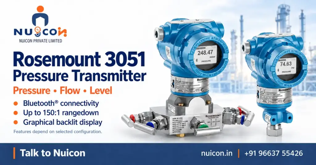
Rosemount 3051 Pressure Transmitter: Full Guide The Rosemount 3051 Pressure Transmitter is an established industrial measurement solution for monitoring pressure across demanding process environments. Depending on the selected configuration, it can measure differential, gauge and absolute pressure, while also supporting flow and level measurement applications. Its combination of measurement accuracy, long-term stability, diagnostic capabilities and communication flexibility makes it suitable for a wide range of process instrumentation requirements. With options such as Bluetooth®, HART®, WirelessHART®, FOUNDATION™ Fieldbus and PROFIBUS®, the transmitter can be integrated into different industrial control and monitoring systems. What Is the Rosemount 3051? A pressure transmitter measures pressure within a process and converts the measurement into a signal that can be used by control and monitoring systems. The Rosemount 3051 extends this function with flexible configurations, digital communication, diagnostics and field-access capabilities for industrial applications. How Does a Pressure Transmitter Work? Pressure Sensing The sensing element detects pressure changes from the connected process. Signal Processing Internal electronics process the sensor output and prepare the measurement for transmission. Data Communication The measured value is transmitted to connected control, monitoring or asset-management systems. Diagnostic Monitoring Available diagnostics provide additional information about selected device and process conditions. Key Features Up to 0.04% Accuracy Selected configurations provide up to 0.04% reference accuracy for demanding pressure measurement requirements. Up to 150:1 Rangedown Wide rangedown provides flexibility when measurement requirements vary across the process. Long-Term Stability Selected configurations are designed to provide up to 10 years of stability. Bluetooth® Connectivity Wireless connectivity allows convenient access to device information and configuration functions. Graphical Backlit Display The local display provides clear visibility of process measurements and transmitter information. Advanced Diagnostics Diagnostic capabilities help provide additional insight into process and device conditions. Flexible Communication Multiple communication options allow the transmitter to suit different industrial control architectures. Measurement Capabilities Differential Pressure Measures the difference between two process pressure points for monitoring, control, flow and level applications. Gauge Pressure Measures process pressure relative to atmospheric pressure. Absolute Pressure Measures pressure against an absolute vacuum reference. Flow Measurement Suitable configurations can support differential-pressure-based flow measurement. Level Measurement Pressure-based configurations can support level measurement in suitable process vessels and systems. Advanced Diagnostic Capabilities Plugged Impulse Line Detection Helps identify potential impulse-line blockage that could affect pressure measurement. Loop Integrity Provides information about electrical loop conditions that may influence signal performance. Process Alerts Helps highlight selected process or device conditions that require attention. Device Diagnostics Provides additional information that can assist with troubleshooting and maintenance activities. Communication & Connectivity 4–20 mA HART® Provides a widely used communication interface for industrial measurement and control systems. WirelessHART® Selected configurations can support wireless communication within suitable plant architectures. FOUNDATION™ Fieldbus Available configurations can support digital fieldbus-based instrumentation systems. PROFIBUS® Selected configurations provide compatibility with PROFIBUS® industrial communication networks. Bluetooth® Provides convenient wireless access for configuration and device interaction. Design & Configuration Coplanar™ Technology The Coplanar platform provides a flexible mounting approach for suitable pressure measurement installations. Flexible Configuration Different configurations allow the transmitter to be matched to measurement type, range and process requirements. Local Display A graphical backlit display provides convenient access to process and device information. Safety Options Selected configurations are available with SIL 2/3 certification options for applicable safety-related applications. Technical Specifications Specification Details Product Type Pressure Transmitter Measurement Types Differential, Gauge & Absolute Reference Accuracy Up to 0.04% Rangedown Up to 150:1 Stability Up to 10 years Communication 4–20 mA HART® Wireless Communication WirelessHART® options Digital Communication FOUNDATION™ Fieldbus & PROFIBUS® options Wireless Connectivity Bluetooth® Display Graphical Backlit Display Diagnostics Loop Integrity, Plugged Impulse Line & Process Alerts Applications Pressure, Flow & Level Safety Options SIL 2/3 configurations Mounting Coplanar™ and configuration-dependent options Pressure Range Configuration dependent Specifications may vary according to the selected model and configuration. Industrial Applications Oil & Gas Supports pressure measurement across production, processing and pipeline operations. Chemical Processing Suitable for monitoring pressure and process conditions in chemical manufacturing systems. Power Generation Supports pressure, flow and level measurement across power generation processes. Water & Wastewater Helps monitor pressure and process conditions in treatment and distribution systems. Pharmaceutical Processing Suitable for selected process and utility measurement applications. Process Manufacturing Supports pressure monitoring across automated production and processing operations. Pump & Pipeline Systems Helps monitor pressure conditions across pumps, pipelines and connected equipment. Flow Measurement Suitable configurations can support differential-pressure-based flow measurement systems. Benefits of the Rosemount 3051 Measurement Flexibility Multiple measurement types and configurations help accommodate different process requirements. Broad Communication Options Communication choices allow integration with different plant control and instrumentation systems. Useful Diagnostic Information Diagnostic functions provide additional information to support monitoring and troubleshooting. Convenient Field Access Bluetooth® connectivity and the graphical display can simplify device interaction. Long-Term Performance Extended stability specifications support applications requiring consistent measurement over time. How to Select the Right Configuration Identify the Measurement Type Determine whether the application requires differential, gauge or absolute pressure measurement. Define the Pressure Range Consider normal and maximum process pressure before selecting the appropriate measurement range. Review Process Conditions Evaluate process temperature, media compatibility, vibration and environmental conditions. Choose Communication Select the communication protocol required by the existing control or monitoring system. Consider Diagnostic Requirements Identify which diagnostic capabilities are relevant to the process and maintenance strategy. Check the Process Connection Confirm the required connection, materials and installation arrangement before ordering. Installation Considerations Select an Appropriate Location Choose an installation point that suits the process and environmental conditions. Plan Impulse Lines Carefully Proper impulse-line routing can help reduce measurement problems and maintenance requirements. Consider Temperature and Vibration Evaluate temperature variations and vibration at the proposed installation location. Provide Maintenance Access Position the transmitter where technicians can inspect and configure the device when required. Follow Product Requirements Installation and commissioning should follow the applicable product documentation and site procedures. Maintenance & Troubleshooting Check Diagnostic Information Review available diagnostic messages when unexpected measurements or alerts occur. Inspect Impulse Lines Check for potential blockage when abnormal pressure readings or diagnostic indications appear. Verify Configuration Review measurement range, output
Rosemount 4051S Pressure Transmitter:- Features, spec and applications
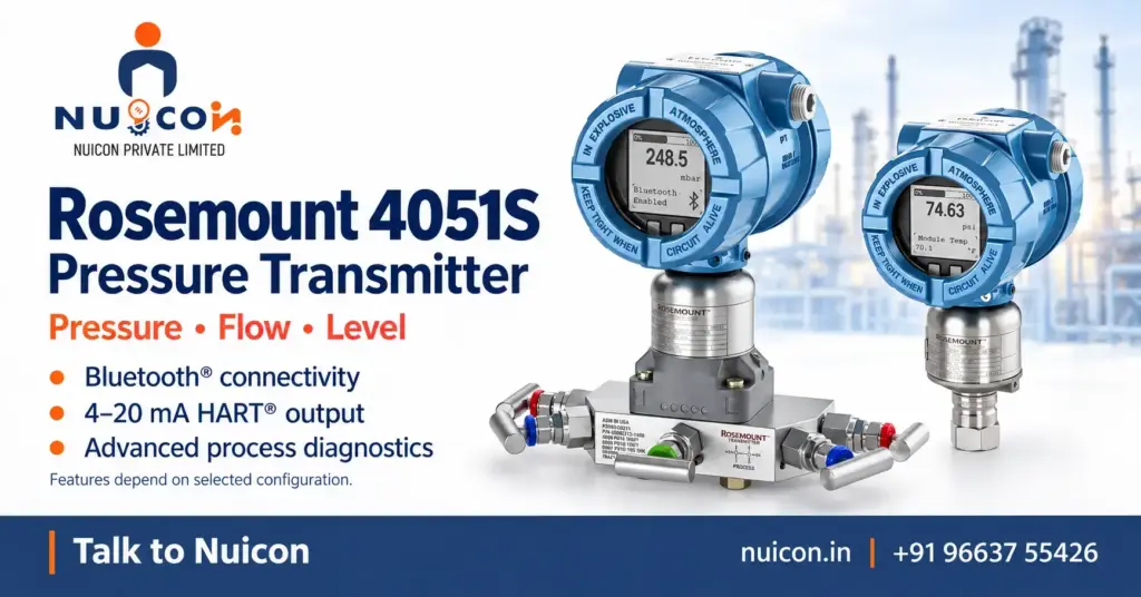
Rosemount 4051S Pressure Transmitter: Features, Specs & Applications The Rosemount 4051S Pressure Transmitter is designed for industrial processes where accurate and consistent pressure measurement is essential. Depending on the configuration, it can measure differential, gauge and absolute pressure, with options for flow and level applications. It combines measurement accuracy with wide rangedown, extended stability, intelligent diagnostics and digital connectivity. These capabilities make it suitable for process environments where reliable measurement and useful device information are important for operation, control and maintenance. What Is the Rosemount 4051S? A pressure transmitter measures process pressure and converts it into a signal that can be used by industrial control and monitoring systems. The Rosemount 4051S adds configurable measurement options, diagnostic functions and field connectivity to support modern process instrumentation requirements. How Does a Pressure Transmitter Work? Pressure Sensing The sensing element detects changes in pressure from the connected process. Signal Processing Internal electronics process the sensor signal and prepare it for industrial transmission. System Integration The measured value can be communicated to control, monitoring and asset-management systems. Diagnostic Monitoring Diagnostic functions provide additional information about selected process and device conditions. Key Features Up to 0.025% Accuracy Selected configurations provide up to 0.025% reference accuracy for demanding measurement applications. Up to 800:1 Rangedown Wide rangedown provides greater flexibility when measurement requirements change across the process. Up to 20-Year Stability Selected configurations are designed for extended measurement stability over long operating periods. Bluetooth® Connectivity Wireless connectivity provides convenient access for configuration and field device interaction. Graphical Backlit Display The local display makes process values and device information easier to view. 4–20 mA HART® Communication Provides a familiar communication interface for industrial control and instrumentation systems. Integral Relay Options Selected configurations can combine pressure measurement with relay-based switching functionality. Advanced Diagnostic Capabilities Process Intelligence Provides additional process information to help users understand changing operating conditions. Plugged Impulse Line Detection Helps identify potential impulse-line blockage that could affect pressure measurement. Loop Integrity Provides information about electrical loop conditions that may influence signal performance. Process Alerts Highlights selected process or device conditions that may require operator attention. Proof-Test Support Available proof-testing functions can assist with instrument verification and maintenance activities. Measurement Capabilities Differential Pressure Measures the pressure difference between two process points for applications such as flow and level measurement. Gauge Pressure Measures process pressure in relation to atmospheric pressure. Absolute Pressure Measures pressure against an absolute vacuum reference. Flow Measurement Specific configurations can support differential-pressure-based flow measurement. Level Measurement Suitable configurations can support pressure-based level measurement in process vessels and systems. Connectivity and Field Configuration 4–20 mA HART® Supports integration with established industrial measurement and control systems. Bluetooth® Provides wireless access to device information and configuration functions where supported. Local Display The graphical backlit display provides convenient access to process and device information. Design for Industrial Applications Hermetically Welded Sensor Platform The welded sensor construction is designed to support operation in demanding industrial environments. Pressure Protection The sensor architecture is designed to help manage the effects of pressure-related stresses on measurement performance. Flexible Configurations Multiple configurations allow the transmitter to be selected according to measurement type, range and application. Safety Options Selected configurations are available with SIL 2/3 certification options for applicable safety-related applications. Technical Specifications Specification Details Product Type Pressure Transmitter Measurement Types Differential, Gauge & Absolute Reference Accuracy Up to 0.025% Rangedown Up to 800:1 Stability Up to 20 years Communication 4–20 mA HART® Wireless Connectivity Bluetooth® Display Graphical Backlit Display Diagnostics Process Intelligence, Loop Integrity, Plugged Impulse Line & Process Alerts Relay Function Available on selected configurations Applications Pressure, Flow & Level Proof Testing Available Safety Options SIL 2/3 configurations Pressure Range Configuration dependent Specifications may vary according to the selected model and configuration. Pressure Range and Configuration Selecting the appropriate pressure range is important for achieving the required measurement performance. Differential and Gauge Pressure Selected Coplanar configurations support differential and gauge pressure measurement up to 2,000 psi (137.9 bar). Absolute Pressure Selected Coplanar configurations support absolute pressure measurement up to 4,000 psia (275.8 bar). Higher-Pressure Measurement Selected In-Line configurations can support gauge and absolute pressure measurement up to 10,000 psi. The appropriate range and configuration should be selected according to the actual process conditions. Industrial Applications Oil & Gas Supports pressure monitoring across production, processing and pipeline systems. Chemical Processing Suitable for pressure measurement across demanding chemical process operations. Power Generation Supports pressure, flow and level measurement across power-related processes. Water & Wastewater Helps monitor pressure and process conditions across treatment and distribution systems. Pharmaceutical Processing Suitable for selected process and utility measurement requirements. Process Manufacturing Supports pressure monitoring across automated production and processing operations. Pump and Pipeline Systems Helps track pressure conditions across pumping systems and connected pipelines. Flow Measurement Selected configurations can support differential-pressure-based flow measurement systems. Benefits of the 4051S Measurement Flexibility Wide rangedown and multiple measurement options help accommodate different process requirements. Additional Process Information Diagnostic functions provide useful information beyond the primary pressure reading. Convenient Field Access Bluetooth® connectivity can simplify device access during configuration and maintenance. Long-Term Measurement Capability Extended stability specifications support applications requiring sustained measurement performance. Flexible System Integration Communication and configuration options allow the transmitter to fit different instrumentation architectures. How to Select the Right Configuration Identify the Measurement Type Determine whether the application requires differential, gauge or absolute pressure measurement. Define the Pressure Range Consider normal, minimum and maximum process pressures before selecting the appropriate range. Check Process Conditions Review process temperature, media compatibility, vibration and environmental conditions. Select Communication Choose the communication method required by the control and monitoring system. Consider Diagnostic Requirements Identify the diagnostic functions that are relevant to the process and maintenance strategy. Review the Process Connection Confirm the required connection, materials and installation arrangement before ordering. Installation Considerations Choose the Installation Location Select a location appropriate for the process, environmental and operating conditions. Plan Impulse Lines Properly Good impulse-line routing can help minimise measurement issues and maintenance requirements. Consider Temperature and Vibration Evaluate temperature variation and vibration when