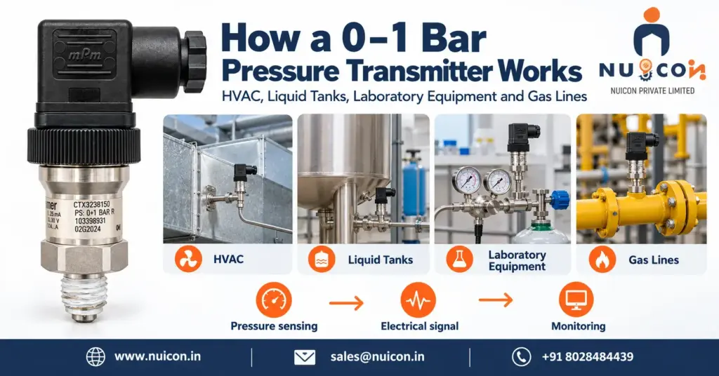
A 0–1 bar pressure transmitter measures pressure from 0 to 100 kPa (approximately 14.5 psi) and converts it into an electrical signal, commonly 4–20 mA. Accuracy, sensing technology, diaphragm construction and overload capability depend on the selected model. The examples below assume a gauge-pressure model with a linear 0–1 bar, 4–20 mA output.
The following sections explain potential applications and the conditions that determine whether this range is suitable.
1. HVAC Systems (Heating, Ventilation, and Air Conditioning)
In HVAC, a 0–1 bar transmitter may monitor a water circuit whose operating and maximum pressures suit the instrument. Ventilation ducts, cleanrooms and air filters usually require much lower pressure ranges expressed in pascals (Pa). A 1 bar full scale equals 100,000 Pa and is generally unsuitable for these small air-pressure differences.
Example: a compatible HVAC water circuit at 0.5 bar produces an ideal 12 mA signal for a BMS.
- The Problem: Water-circuit pressure must remain within the system’s design limits. Separately, air-filter loading and room-pressure control require measurements of small pressure differences.
- How the Transmitter Works: For a suitable water circuit, the process connection transmits fluid pressure to the sensing assembly. Electronics convert the sensor response into the specified output.
- Choose the range for normal pressure, maximum possible pressure and required accuracy. Taller buildings or higher-pressure circuits may need a range above 0–1 bar.
- For ventilation filter monitoring, use a suitably ranged differential-pressure instrument connected upstream and downstream of the filter. A single gauge-pressure measurement does not establish filter pressure drop.
- The System Reaction: The BMS can display pressure and initiate configured alarms or control actions. Fan airflow control normally uses suitable duct static-pressure or differential-pressure feedback rather than a general-purpose 0–1 bar water-pressure transmitter.
2. Liquid Tank Level (Hydrostatic Level Measurement)
Hydrostatic level measurement uses P = ρgh: liquid pressure depends on density (ρ), gravitational acceleration (g) and liquid height (h) above the sensing point.
As liquid level rises, hydrostatic pressure increases; the controller converts measured pressure into level using the liquid density.
- The Problem: Operators need a continuous level indication without repeatedly accessing the tank. Hydrostatic measurement is suitable when density and the pressure above the liquid are known or compensated.
- How the Transmitter Works: Install a compatible gauge-pressure transmitter at a known elevation near the bottom of an open, vented tank. Using water density 1,000 kg/m³ and g = 9.80665 m/s², 1 m of water produces approximately 0.09807 bar; 10 m produces approximately 0.98067 bar.
- As the tank fills, hydrostatic pressure acts on the sensing assembly. Wetted materials must be compatible with the liquid. A pressurised tank requires compensation for headspace pressure.
- With these assumptions, a 5 m water column produces approximately 0.49033 bar and 11.845 mA on a 0–1 bar transmitter. An ideal 12 mA corresponds to 0.5 bar, or approximately 5.099 m of water.
- The System Reaction: The PLC calculates h = P/(ρg), accounting for sensor elevation and tank calibration. A 5 m reading is 100% of a 5 m usable level span, or 50% of a 10 m span. Percentage volume also depends on tank geometry. Configured pump control and independent overfill protection are selected for the application.
3. Laboratory and Specialized Equipment
Laboratory vessels and test equipment may use a 0–1 bar transmitter where the operating pressure, accuracy, cleanliness, temperature and material requirements match. This range alone does not establish suitability for medical equipment or very low-pressure gas blanketing.
Example: vessel pressure is measured, the controller compares it with a configured setpoint, and a suitable control valve adjusts gas supply or venting.
- The Problem: Some processes require controlled headspace pressure or an inert atmosphere. Excess pressure can damage equipment or disturb the process; inert-gas requirements depend on the chemistry and operating procedure.
- How the Transmitter Works: Connect the instrument at an appropriate pressure tapping. Metallic and ceramic sensor designs are available; select the complete wetted construction for compatibility, cleanliness and any sterilisation requirements.
- The electronics condition the sensor response. Required accuracy, resolution, temperature performance and response time must be checked in the datasheet. A change of 0.001 bar equals 1 mbar and is not a guaranteed measurement capability.
- Pressure can change resistance or capacitance depending on sensor technology. Pressure changes cannot be inferred from gas volume alone without considering temperature and the amount of gas.
- The System Reaction: A controller may adjust gas supply or a vent valve when pressure exceeds a configured limit. A 0.02 bar change is an illustrative setpoint difference, not a universal operating requirement. Control response and protective measures depend on the complete system.
4. Low-Pressure Gas Lines
A 0–1 bar transmitter may monitor compatible gas services within its specified range. Low-pressure burners and gas-blanketing systems may need a much narrower range, particularly when operating at only a few tens of millibar.
Example: falling gas pressure reduces the current; a controller compares it with a low-pressure setpoint and initiates the designed response.
- The Problem: Incorrect gas pressure can affect combustion and equipment operation. Actual supply pressure, appliance requirements, materials and hazardous-area requirements must be established for the installation.
- How the Transmitter Works: Install a gas-compatible transmitter at the designated pressure tapping. A gauge-pressure version measures pressure relative to local atmosphere through its designed atmospheric reference arrangement.
- The sensing assembly responds to the difference between process pressure and its reference pressure.
- Gauge measurement uses local atmosphere as the reference. It does not make gas delivery or equipment operation independent of weather, altitude or other process conditions.
- The System Reaction: On a linear 0–1 bar scale, 0.01 bar produces an ideal 4.16 mA, not an output below 4 mA. A low-pressure alarm uses a configured process setpoint. Where protective shutdown is required, the transmitter, controller, valve, diagnostics and response time must suit the complete protective function.
Selection note: confirm pressure type, normal and maximum pressure, accuracy, wetted materials, temperature limits, output and required approvals before choosing a model.