
What Is a Pressure Transmitter? Meaning, Signal Output and Features of 0–1 Bar vs. 0–4 Bar Models

What Is a Pressure Transmitter? Meaning, Signal Output and Features of 0–1 Bar vs. 0–4 Bar Models Meaning:- A pressure transmitter measures pressure—the force per unit area exerted by a liquid or gas—and provides a conditioned electrical output for a PLC, computer or display. The Analog Analogy As a simple analogy, pressure changes the output smoothly, similar to adjusting a dimmer. The following examples assume a linear, zero-based 4–20 mA pressure scale; the transmitter does not directly drive a lamp. Zero pressure = 4 mA. This is a live zero: the loop carries current even at the lower measurement limit. Half-scale pressure = 12 mA: 0.5 bar on a 0–1 bar model, or 2 bar on a 0–4 bar model. Full-scale pressure = 20 mA: 1 bar on a 0–1 bar model, or 4 bar on a 0–4 bar model. Why is it called a “Transmitter” and not just a “Sensor”? A sensing element responds to pressure through an electrical or mechanical change. The terms sensor, transducer and transmitter overlap in commercial usage. A transmitter includes conditioning electronics and a specified output, such as 4–20 mA. Current loops support remote measurement within their voltage and resistance limits. Correct installation reduces interference, but no transmission method is immune to all noise or wiring faults. 0–1 Bar Pressure Transmitter Features A 0–1 bar model provides a 1 bar measuring span. Suitability depends on the required pressure type, accuracy and application conditions, rather than an assumed trade-off between sensitivity and strength. Sensing Construction: Metallic, ceramic and other sensing designs are available. Range alone does not determine diaphragm thickness or guarantee suitability for low-velocity air measurement. Signal Sensitivity: A linear 4–20 mA version provides 16 mA/bar. This gives four times the current change per bar of a 0–4 bar version. Actual resolution and accuracy remain product- and receiver-dependent. Overpressure Capability: Check the specified permissible overload and burst pressure. Do not assume a 2–3 bar limit from a 0–1 bar measuring range. Burst pressure is not an allowable operating pressure. Pressure Reference: A vented gauge model measures relative to local atmosphere; protect its reference arrangement as instructed. Absolute-pressure and other reference types differ. Atmospheric venting is not unique to the 0–1 bar range. 0–4 Bar Pressure Transmitter Features A 0–4 bar model provides a measuring span four times wider than a 0–1 bar model. It may suit regulated air, water or lubrication services within its specifications. Sensing Construction: Technology and mechanical durability depend on the product family. A thicker diaphragm or more robust sensing die cannot be assumed from the range alone. Measuring Span: A 0–4 bar model covers a 2–3 bar operating condition that is outside a 0–1 bar span. Allow for actual maximum pressure and transients when selecting the instrument. Overpressure Capability: Use manufacturer-specified limits rather than assuming an 8–12 bar proof rating. Confirm how the manufacturer defines overload, proof and burst pressure and any limits on exposure. Pulsation Protection: Check dynamic-pressure suitability. Water hammer and pump pulsations may require a specified snubber, damper or other protection. Internal fill fluid, where present, primarily transmits pressure to the sensing element. Comparison of Core Features Feature 0–1 Bar Transmitter 0–4 Bar Transmitter Primary Focus A 1 bar measuring span; ideal current sensitivity 16 mA/bar. A 4 bar measuring span; ideal current sensitivity 4 mA/bar. Burst Pressure Model-specific; verify the datasheet. Not a permissible operating limit. Model-specific; verify the datasheet. Not a permissible operating limit. Diaphragm Thickness Design-specific; cannot be inferred from range alone. Design-specific; cannot be inferred from range alone. Best Used For Suitable vented-tank level, test rigs or gas services; confirm range, accuracy and materials. Duct air usually requires a much lower range. Suitable regulated air branches, water circuits or lubrication lines within the specified range and ratings. Selection note: compare accuracy on the same basis. For illustration, ±0.5% of span equals ±0.005 bar on a 0–1 bar instrument and ±0.020 bar on a 0–4 bar instrument. These are examples, not specifications for a particular product. Recent Posts What Is a Pressure Transmitter? Meaning, Signal Output and Features of 0–1 Bar vs. 0–4 Bar Models October 24, 2026 How a 0–4 Bar Pressure Transmitter Works: Internal Components and Installation Materials The following describes common construction options and installation… Read More → How a Pressure Transmitter Works: Meaning, Uses, Benefits, Risks of Not Using One, and 0–1 Bar vs. 0–4 Bar Comparison. October 24, 2026 How a Pressure Transmitter Works: Meaning, Uses, Benefits, Risks of Not Using One, and 0–1 Bar vs. 0–4 Bar Comparison… Read More → How a 0–4 Bar Pressure Transmitter Works: Internal Components and Installation Materials October 24, 2026 How a 0–4 Bar Pressure Transmitter Works: Internal Components and Installation Materials The following describes common construction options and installation… Read More → How a 0–4 Bar Pressure Transmitter Works in Pneumatic Systems, Water Treatment, Heating and Cooling Loops, Lubrication and Low-Pressure Hydraulics October 24, 2026 How a 0–4 Bar Pressure Transmitter Works in Pneumatic Systems, Water Treatment, Heating and Cooling Loops, Lubrication and Low-Pressure Hydraulics… Read More → REQUEST A QUOTE
How a 0–4 Bar Pressure Transmitter Works: Internal Components and Installation Materials
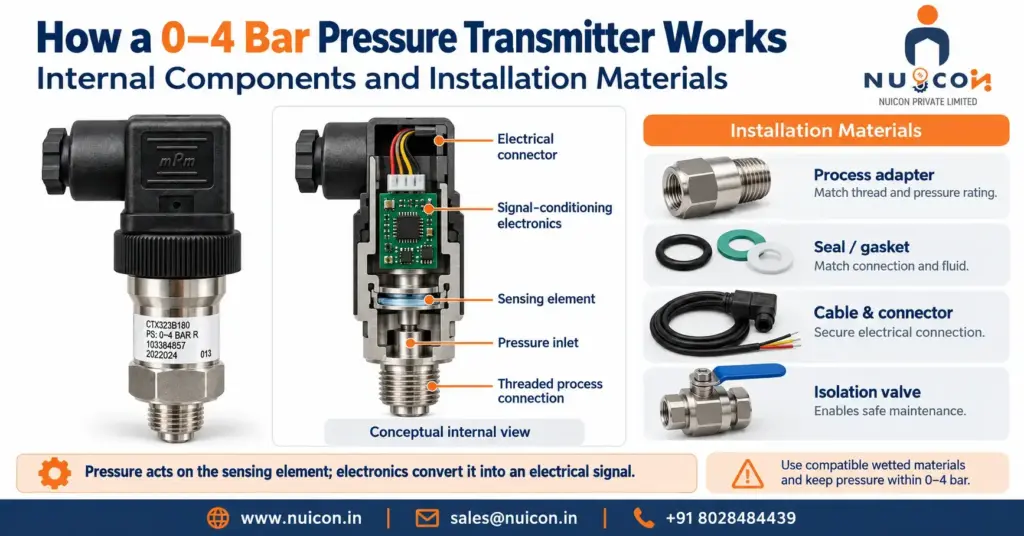
How a 0–4 Bar Pressure Transmitter Works: Internal Components and Installation Materials The following describes common construction options and installation accessories. The exact components and required accessories depend on the selected model and application. Internal Components (Inside the Transmitter) Manufacturers combine a sensing assembly and signal-conditioning electronics; the construction varies between product families. Sensing Element: Common options include piezoresistive silicon, ceramic thick-film, metal thin-film and capacitive designs. Pressure changes resistance or capacitance depending on technology. Range alone does not establish diaphragm thickness, accuracy or overload capability. Process Diaphragm: The pressure-sensitive or isolating surface may be metallic or ceramic. Examples include stainless steel, alumina ceramic and specialist alloys. Verify all wetted materials, including seals, for the process fluid and temperature. Internal Fill Fluid (where used): In some isolated sensing assemblies, a liquid transmits pressure from the process diaphragm to the sensing element. Other designs are oil-free. Fill fluid is not a general substitute for pulsation protection. Oxygen service requires manufacturer-approved materials, cleanliness and construction; oil type alone is insufficient. ASIC/Circuitry: An integrated circuit board that processes the sensor’s physical deflection and calibrates it linearly across the 0 to 4 bar span, outputting a standard industrial signal (e.g., 4–20 mA, 0–10 V, or Modbus). Housing/Enclosure: Material and ingress protection depend on the product and environment. Select suitable protection for dust, washing, condensation or immersion. The stated rating may require the correct mated connector and cable installation. Atmospheric Reference: A vented gauge-pressure transmitter references local atmospheric pressure through an arrangement determined by its design. Protect the reference path from blockage and moisture according to the installation instructions. Absolute-pressure versions use a different reference. External Materials (Needed for Installation & Operation) Provide the accessories required by the installation; adapters and impulse tubing are unnecessary where a suitable direct connection is available. 1. Mechanical Piping & Process Connection Process Fitting: Match the exact transmitter connection, sealing face and pressure/temperature rating. Common options include G1/4, G1/2, 1/4 NPT and 1/2 NPT, but these are not interchangeable. Sealing Material: For tapered NPT connections, use an approved thread sealant where specified and avoid contaminating the pressure port. For parallel G connections, use the specified face seal, washer or O-ring. Choose FKM, EPDM, metal or another material by chemical compatibility, temperature and connection design; 4 bar alone does not determine the correct seal. Isolation Valve (where required): Select a compatible valve for the maximum possible pressure and temperature, including abnormal conditions. Provide safe depressurisation before removing or calibrating the transmitter; closing a valve alone may leave trapped pressure. Siphon, Cooling Element or Snubber (where required): Check the permissible medium temperature and transient pressure. A suitable siphon can protect an instrument in steam service; cooling elements or remote mounting may suit other hot services. A specified snubber or pulsation damper may be required for pressure spikes. Select and install accessories for the actual process. 2. Electrical Materials Power Supply: 24 VDC is common, but use the model’s specified voltage range. For a two-wire loop, allow sufficient voltage for the transmitter, receiver, wiring resistance and any barriers or isolators. Cabling / Wiring: Use the specified cable and wiring arrangement. A two-wire 4–20 mA transmitter commonly uses a twisted pair; voltage or digital versions may need additional conductors. Correct shielding and routing reduce electromagnetic interference. Select conductor size for loop resistance and installation conditions. Mating Connector: Match the specified connector form, pinout, seal and protection rating, such as the applicable EN 175301-803 (formerly DIN 43650) form or M12 version. For hazardous areas, the transmitter and installation must have appropriate approvals; a certified gland does not upgrade an ordinary transmitter. 3. Control & Monitoring System Receiver Device: A PLC (Programmable Logic Controller) analog input card, a DCS, or a Digital Panel Indicator calibrated to read the electrical output and map it to a display of 0.0 to 4.0 bar. Grounding / Shielding: Follow the manufacturer’s instructions and plant bonding requirements. Use any specified earth terminal and terminate shields as designed. Correct bonding reduces electrical risks and interference; it does not guarantee elimination of stray voltages. Installation note: follow the model’s instructions for mounting, wiring, shielding, bonding and commissioning. Confirm zero and span scaling against the receiver and use pressure protection where the application requires it. Recent Posts How a 0–4 Bar Pressure Transmitter Works: Internal Components and Installation Materials October 24, 2026 How a 0–1 Bar Pressure Transmitter Works: Internal Components and Installation Materials The following describes common construction options and installation… Read More → How a 0–4 Bar Pressure Transmitter Works in Pneumatic Systems, Water Treatment, Heating and Cooling Loops, Lubrication and Low-Pressure Hydraulics October 24, 2026 How a 0–4 Bar Pressure Transmitter Works in Pneumatic Systems, Water Treatment, Heating and Cooling Loops, Lubrication and Low-Pressure Hydraulics… Read More → How a 0–1 Bar Pressure Transmitter Works: Internal Components and Installation Materials October 24, 2026 How a 0–1 Bar Pressure Transmitter Works: Internal Components and Installation Materials The following describes common construction options and installation… Read More → How a 0–1 Bar Pressure Transmitter Works in HVAC, Liquid Tanks, Laboratory Equipment and Gas Lines October 24, 2026 How a 0–1 Bar Pressure Transmitter Works in HVAC, Liquid Tanks, Laboratory Equipment and Gas Lines A 0–1 bar pressure… Read More → REQUEST A QUOTE
How a 0–1 Bar Pressure Transmitter Works: Internal Components and Installation Materials
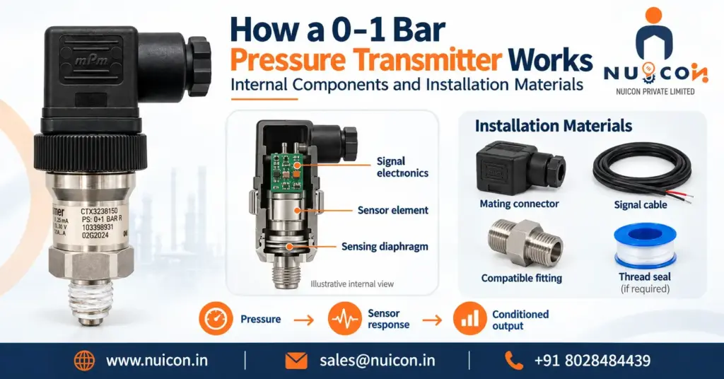
How a 0–1 Bar Pressure Transmitter Works: Internal Components and Installation Materials The following describes common construction options and installation accessories. The exact components and required accessories depend on the selected model and application. Internal Components (Inside the Transmitter) Manufacturers combine a sensing assembly and signal-conditioning electronics; the construction varies between product families. Sensing Element: Common options include piezoresistive silicon, ceramic thick-film, metal thin-film and capacitive designs. Pressure changes resistance or capacitance depending on technology. Range alone does not establish diaphragm thickness, accuracy or overload capability. Process Diaphragm: The pressure-sensitive or isolating surface may be metallic or ceramic. Examples include stainless steel, alumina ceramic and specialist alloys. Verify all wetted materials, including seals, for the process fluid and temperature. Internal Fill Fluid (where used): In some isolated sensing assemblies, a liquid transmits pressure from the process diaphragm to the sensing element. Other designs are oil-free. Fill fluid is not a general substitute for pulsation protection. Oxygen service requires manufacturer-approved materials, cleanliness and construction; oil type alone is insufficient. ASIC/Circuit Board: Internal electronics that amplify, linearize, and convert the tiny sensor fluctuations into a standard industrial signal (like 4–20 mA or 0–10 V). Housing/Enclosure: Material and ingress protection depend on the product and environment. Select suitable protection for dust, washing, condensation or immersion. The stated rating may require the correct mated connector and cable installation. Atmospheric Reference: A vented gauge-pressure transmitter references local atmospheric pressure through an arrangement determined by its design. Protect the reference path from blockage and moisture according to the installation instructions. Absolute-pressure versions use a different reference. External Materials (Needed for Installation & Operation) Provide the accessories required by the installation; adapters and impulse tubing are unnecessary where a suitable direct connection is available. 1. Mechanical Piping & Process Connection Process Fitting: Match the exact transmitter connection, sealing face and pressure/temperature rating. Common options include G1/4, G1/2, 1/4 NPT and 1/2 NPT, but these are not interchangeable. Sealing Material: Use an approved sealant for tapered threads where specified. Parallel G connections normally seal at a designated face using the specified washer or O-ring. Select seals for the medium, temperature and connection geometry; follow the manufacturer’s assembly instructions. Impulse Piping / Tubing (where required): Select compatible tubing for pressure, temperature and fluid service. Account for leaks, blockage, trapped gas or liquid, and hydrostatic offsets. Direct mounting may eliminate the need for tubing. Isolation Valve (where required): Select a compatible valve for the maximum possible pressure and temperature, including abnormal conditions. Provide safe depressurisation before removing or calibrating the transmitter; closing a valve alone may leave trapped pressure. 2. Electrical Materials Power Supply: 24 VDC is common, but use the model’s specified voltage range. For a two-wire loop, allow sufficient voltage for the transmitter, receiver, wiring resistance and any barriers or isolators. Cabling / Wiring: Use the specified cable and wiring arrangement. A two-wire 4–20 mA transmitter commonly uses a twisted pair; voltage or digital versions may need additional conductors. Correct shielding and routing reduce electromagnetic interference. Select conductor size for loop resistance and installation conditions. Mating Connector: Match the specified connector form, pinout, seal and protection rating, such as the applicable EN 175301-803 (formerly DIN 43650) form or M12 version. For hazardous areas, the transmitter and installation must have appropriate approvals; a certified gland does not upgrade an ordinary transmitter. 3. Control & Monitoring System Receiver Device: An instrument to read and scale the electrical signal, such as a Digital Panel Meter, a PLC (Programmable Logic Controller), or a DCS (Distributed Control System) input card. Loop Resistor (if applicable): A suitable 250 Ω resistor converts 4–20 mA into 1–5 V across it. Use this only with an appropriate voltage input and adequate loop voltage. Do not automatically add a resistor across a current input; account for its existing resistance and follow the receiver wiring instructions. Installation note: follow the model’s instructions for mounting, wiring, shielding, bonding and commissioning. Confirm zero and span scaling against the receiver and use pressure protection where the application requires it. Recent Posts How a 0–1 Bar Pressure Transmitter Works: Internal Components and Installation Materials October 24, 2026 Rosemount 3051 Pressure Transmitter: Full Guide The Rosemount 3051 Pressure Transmitter is an established industrial measurement solution for monitoring pressure… Read More → How a 0–1 Bar Pressure Transmitter Works in HVAC, Liquid Tanks, Laboratory Equipment and Gas Lines October 24, 2026 How a 0–1 Bar Pressure Transmitter Works in HVAC, Liquid Tanks, Laboratory Equipment and Gas Lines A 0–1 bar pressure… Read More → Rosemount 3051 Pressure Transmitter:- Full guide September 22, 2026 Rosemount 3051 Pressure Transmitter: Full Guide The Rosemount 3051 Pressure Transmitter is an established industrial measurement solution for monitoring pressure… Read More → Rosemount 4051S Pressure Transmitter:- Features, spec and applications September 19, 2026 Rosemount 4051S Pressure Transmitter: Features, Specs & Applications The Rosemount 4051S Pressure Transmitter is designed for industrial processes where accurate… Read More → REQUEST A QUOTE